Evaluation of Hysteresis Property of Piezo
Actuator by Moire Interference Method
Hiroyuki Masuda
Corrosion
Analysis Group , National Institute for Metals Science
1-2-1
Sengen Tukba Ibaraki Japan 305
Abstract
The scanning prove microscopes (SPM) are now commonly used in
studying micro-structures and micro-processing. The SPM can be used
not only to observe the surface of materials but also to fabricate
very small structures. However the accuracy of the SPM image is
usually unknown around the range between 50 and 500 nm, because no
proper standard material exists to get the hysteresis property of the
piezo actuator. When we observe the automically flat surface by SPM,
we can often find noise-like pattern around the scanning range of 50
to 200 nm. This pattern is moire pattern produced by atoms or
molecular. We applied this moire pattern to the measurement of the
hysteresis property of the piezo actuator around the range between 50
and 500 nm. The results show that this method is very accurate and
useful to measure the hysteresis property of the piezo actuator.
Keywords: Hysteresis Property, Piezo Actuator , Moire Interference
Method, Mica, SPM
Introduction
The scanning prove microscopes (SPM), such as the scanning tunneling
microscope (STM) and the atomic force microscope (AFM), are now
commonly used in studying micro-structures and micro-processing. The
SPM can be used not only to observe the surface of materials but also
to fabricate very small structures. However the accuracy of the SPM
image is usually unknown around the range between 50 and 500 nm,
because no proper standard material exists to get the hysteresis
property of the piezo actuator. Moire interference method is often
used to measure the strain distribution, because the strain change
can be measured more accurately than the direct measurement method.
When we observe the automically flat surface by SPM, we can often
find noise-like pattern around the scanning range of 50 to 200 nm.
This pattern is moire pattern produced by atoms or molecular. We
discuss the application of this moire pattern to the measurement of
the hysteresis property of the piezo actuator around the range
between 50 and 500 nm.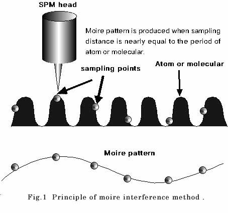
Principle
Figure 1 shows the principle of moire interference method. Moire
interference method can be used for atoms and molecular arranged
regularly. Moire pattern usually appear when the sampling distance is
nearly equal to the period of atoms or molecular. Two types of Moire
pattern is considered. One is that moire pattern produced when the
sampling distance is smaller than the period of atoms or molecular
Pf, and the other is that moire pattern produced when the sampling
distance is bigger than the period of atoms or molecular. We call the
former moire pattern positive moire pattern and the later negative
moire pattern. The relation between moire pattern spacing d and the
sampling distance Pc is written as:
for positive moire pattern 1/d = 1/Pc - 1/(1 + e)Pf (1)
for negative moire pattern 1/d = 1/(1 + e)Pf - 1/Pc (2)
where e is the strain.
We can determine the hysteresis property by these equations.
Experiment
The specimen used was mica (15 x 15 x 0.5 mm). The AFM used was
SP7000(SEIKO). Test was performed at 23C in air with scanning range
of 15 to 200 nm, scanning speed of 2 mm/s, sampling data of 256 x 256
and tip-force of 0.2 nN.
Results and Discussion
We first took the AFM image of mica molecular with scanning range of
15 nm. Figs. 2(a) and 2(b) show the AFM image of mica molecular with
and without FFT treatment. The period of molecular at horizontal
direction is found about 0.55 nm. Moire pattern appears when the
sampling distance is nearly equal to the period of molecular, that
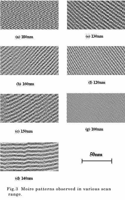
is, 0.55 x 256 = 140.8 nm. Figs. 3(a) - 3(g) show moire patterns
observed in various scan range. As we expected, the moire pattern
spacing is the biggest at the scan range of 140 nm. Moire patterns
produced at the scan range smaller than 140 nm correspond to positive
moire pattern and produced at the scan range bigger than 140 nm
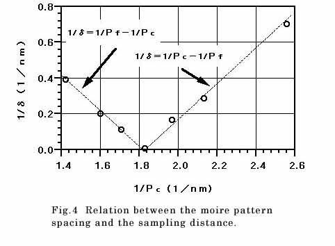
correspond to negative moire pattern. Fig. 4 shows the relation
between the moire pattern spacing and the sampling distance, where
the moire pattern spacing was obtained from the averaging the image
data at the center part (100 pixels). The broken line shows the
theoretical curves expressed as equations (1) and (2). It is clear
that the observed moire pattern spacing coincides with the
theoretical curves. However, the moire pattern spacing as shown in
Figs. 3 should be the same in whole scanned area if no hysteresis
exists in the piezo actuator. The change of the moire pattern spacing
is caused by the hysteresis property of the piezo actuator.
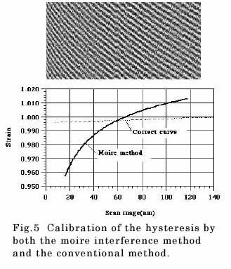
Calibration of the hysteresis property was done by using Fig. 3(e).
Fig. 5 shows the calibration of the hysteresis by both the moire
interference method and the conventional method (estimated from the
large standard sample). The difference of strain accuracy exceeds
more than 4%. If we use the horizontal sampling data of 512, we can
observe the moire pattern around the scan range of 280 nm in this
material. In this way, we can calibrate the wider range of hysteresis
on the piezo actuator.
Conclusion
Moire interference method is very convienient to calibrate the
hysteresis property of piezo actuator. Mica or graphite is standard
material to calibrate the SPM accuracy and easy to get. Using this
method, we can get more accurate image around 50 to 500 nm.