Practical method for coma-free alignment using caustic figure
Coma-free alignment is important in high-resolution transmission electron microscopy (HRTEM). After a pioneering study by Zemlin 1, a variety of alignment procedures have been proposed, such as beam-tilt-induced astigmatism (TIA), beam-tilt-induced focus change (TIF) and beam-tilt-induced image displacement (TID) methods 2,3. The previous methods basically require plural HRTEM images observed as beam tilting. We provide a practical way for coma-free alignment using a single defocused TEM image without intentional beam tilting 4.
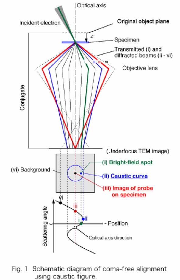
The procedure is schematically depicted in Figure 1. The specimen position is shifted from the original object plane toward the objective lens by several microns. The TEM image on the observed plane corresponds to an underfocused image. The incident electron beam is focused on the specimen. Transmitted electrons are observed as (i) a bright-field spot on the observed image plane. Due to the spherical aberration, the scattered electron at a certain angle (thick line) forms a caustic surface, which is observed as (ii) a caustic curve. A part of more highly scattered electrons (broken line) is focused on the observed image plane, and is observed as (iii) the image of the probe on the specimen. Further highly scattered electrons (dotted line) form (iv) background outside the caustic curve.
The present alignment method employs a caustic curve for finding the optical axis. Note that the positions of (ii) the caustic curve and (iii) the image of the probe do not depend on the incident beam direction. By contrast, the position of (i) bright-field spot moves according to the incident beam direction. The alignment can be performed by coinciding the bright-field spot with the center of the caustic curve (or the image of the probe) by tilting the incident beam.
In complex notation the wave aberration c(w) is written as 2,
![]()
![]() , (1)
, (1)
where w is scattering angle, Cs the spherical aberration coefficient, z the defocus, d image displacement, and b coma aberration. a2 and a3 denote the two-fold and three-fold astigmatism coefficients, respectively. Complex numbers are denoted by bold italics, and an overbar a complex conjugate. In the present alignment procedure, we measure the position of the probe scattered by the specimen as the caustic curve. Tilt-induced image displacement d(w) and tilt-induced coma b(w) by the additional tilt w are,
![]() , (2)
, (2)
![]() , (3)
, (3)
where b0 is inherent coma. The image displacements are calculated using Eq. (2). Coma aberration has the effect to shift the caustic curve from the center. This off-center property is important in detecting coma aberration. According to Eq. (3), the beam tilt required for coma-free alignment is -b0/2Cs, and it corresponds to the center of caustic curve, therefore our alignment procedure provide coma-free alignment. The experimental results and detailed discussions are described in the reference [4].
References
[1] Zemlin, F.et al. (1978) Ultramicroscopy 3, 49.
[2] Ishizuka, K. (1994) Ultramicroscopy 55, 407.
[3] Krivanek, O.L. (1994) Ultramicrosocpy 55, 419.
[4] Kimoto, K., et al.(2003) Ultramicroscopy 96, 219.